Lab 9 Overview
In lab 9, students wrote code which mapped an arena in the lab. The code took ToF measurements in between in-place rotations that spanned 360 degrees. The robot executed the code at 5 spots throughout the map. By converting the position of the perceived obstacle in the robot’s frame to the global frame, a map of the arena was developed.
Code overview
Pseudo code for my mapping function is shown below. My code used a PD controller to change its orientation based upon feedback from the onboard ToF sensor. Once at a measurement location, 3 ToF sensor measurements were taken and averaged. ToF values were stored and returned to the robot via a notification handler.
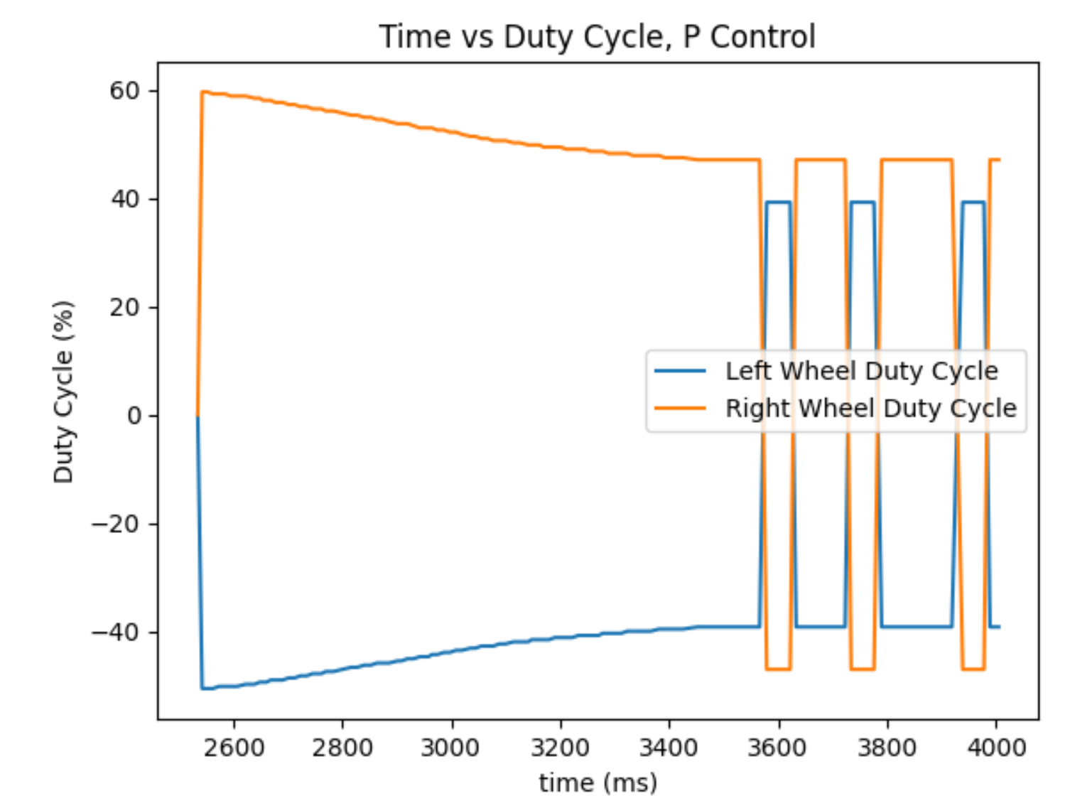
The PD controller for yaw was borrowed from labs 6 and 8. As the robot rotates towards its target angular position, the duty cycles sent to the motors varied as seen in the graph below from lab 6.

Executing Code
The video below shows the robot executing the code, rotating to specified positions, and taking ToF measurements. Note that the robot moved off of its starting point, which was a recurring issue while I conducted this lab.
Data
In the polar coordinate plots below, the ToF data is shown centered at the five points that the robot rotated about. The distances are in meters
Post Processing and Analysis
To convert the data from the robot frame to the global frame, transformation matrices were used. A transformation matrix is an encoding of a rotation and translation that differentiate the point of view of one coordinate system and another. In two dimensions, a transformation matrix has the form shown below. The notation BI stands for body to inertial, so R_BI is the rotation matrix to go from the body fixed frame to the inertial frame, if the two coordinate systems shared the same origin. The pos is the x,y coordinate of the robot in the inertial/global frame. Multiplying a point in the body frame by the transformation matrix BI will return the coordinates of the point in the inertial frame. In the case of ToF measurements, because the sensor points towards the body frame x-axis, all reading locations have only an x component in the body frame.
When the data from all the different rotation locations is overlaid, the following plot results. My manual estimation of the walls given the data points are drawn in. The map is far from perfect which I attribute to two things. One, as seen in the previous video, the robot translates during rotation. This not only means that the robot may see an obstacle as too close or too far, but it may encounter an obstacle that it never would on the correct spot or vice versa. Additionally, the timescale of the total rotation was enough for gyroscope drift to noticeably affect the position. The robot was supposed to end at 340 degrees every trial, but it sometimes went past one full rotation.